Overview of A.MANNESMANN Ball Screws
Ball screws are screw drives that convert a rotating drive motion into a linear motion in normal operation. Due to the favorable friction conditions and the associated very high degree of efficiency (>90%), they are in principle not self-braking so that in reverse operation a linear drive motion can also be implemented in the rotational direction.
Standard Applications with Precision Requirements
The standard applications of ball screws include all of the applications that do not need to be assigned to any particular application requirement. The requirements with respect to accuracy, load bearing capacity and dynamics are considerable, but can easily and safely be realized with the precision ball screws of A.MANNESMANN.
DIN-Compliant Positioning and Transport Ball Screws
The standard ball screws from A.MANNESMANN are equipped with double nuts with a side flange. They have preloaded bearing balls in an O-arrangement and can be used both as positioning and as transport ball screws. The nut dimensions and the technical characteristics are based on DIN ISO 3408 or DIN 69051.
Accuracy in All Installation Positions with the Best Values
AM ball screws are produced in the accuracy classes IT 1, IT 3 or IT 5. They are generally equally well-suited for horizontal and vertical operation. The axial force loads of the preloaded ball screws normally bear a maximum of 30% of the dynamic load rating. Usually significantly more than 20,000 hours of operation are reached at a standard travel speed and acceleration.

Technical advantages
- The highest power transmission rates
- Extremely high degree of efficiency (up to 98%)
- Perfect positioning capability and repeatability
- High load capacity
- Exact travel movements
- High rigidity
- Ball screw spindles with ground precision (accuracy IT 1, IT 3, IT 5)
- Constant torque
- Extremely low power losses
- Uniformly low operating temperatures
- Can be used in all installation positions
Design of Ball Screws
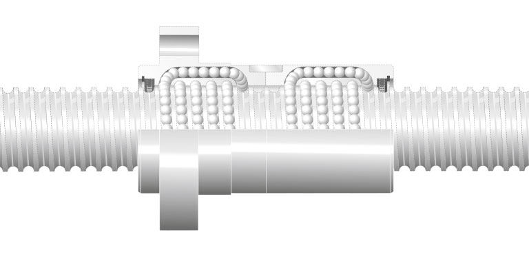
Ball screws essentially consist of a ballscrew , a ballnut and a large number of balls. The balls make the connection between the ballscrew and the ballnut and are used as a force and movement-transmitting rolling element. The rolling balls roll very precisely in the loaded turns on the ballscrew and in theballnut.
Ball screws are primarily designed for the safe transmission of axial forces. Their force curve occurs via the effective direction of the pressure curves through the balls. With the O-arrangement of the balls, they run with the tip to the outside and with the X-arrangement they run with the tip to the inside. The effective direction of the pressure curves is not only important for the distribution of forces, but also for the generation of the preload.
Dynamics and Precision of Ball Screws
Ball screws together with their support bearing and the drive elements form heavy duty, very dynamic and extremely accurate drive units to, for example, generate advance movements of machine tools. Due to the high load capacity and the tremendous precision, they have proven themselves excellently over decades and are still today a very innovative machine element with a future.
Balls and Ball Recirculation Systems
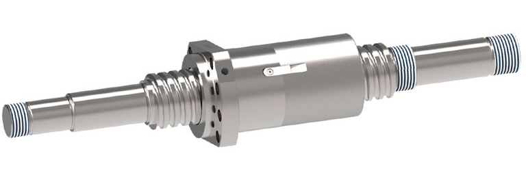
The spatial arrangement of the balls corresponds to that of an endless chain. It therefore not only forms in the loaded turns, but also in the ball return through which the balls must be returned axially to the starting point from the end point of the contact movement between the spindle and the nut. Different basic principles have proven themselves as ball recirculation systems in various design versions (e.g. external and internal return with total, single-run or pipe deflection). Since every ball return has advantages and disadvantages, the correct selection for the application is particularly important in order to achieve the greatest possible realization of the requirements and the best possible functionality.
Ball track of a double nut with total deflection
Two Basic Principles: Driven Nut or Driven Spindle
Ball screws are divided into two basic structural principles after the component that initiates the rotational movement:
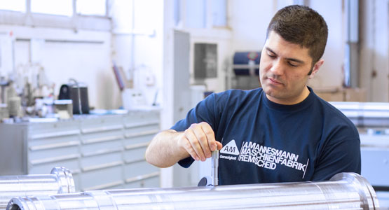
- Ball screw with driven spindle and stationary nut (type AM 2.51)
- Ball screw with driven nut and stationary spindle (type AM 2.52)
Most ball screws are designed with a driven spindle. The rotation of the spindle is then converted into a linear displacement movement of the nut relative to the spindle. This design is also called a normal configuration.
Depending on the task, the design version with a driven nut may be more advantageous under certain circumstances. The rotating drive movement of the nut is converted here into a translatory movement of the spindle relative to the nut. Compared to driven spindles, driven nuts can achieve longer travels, higher rpms and therefore also higher travel speeds. In addition, it is possible to place several nuts on one spindle and to move these individually with separate drives.
In both cases (driven spindles and driven nuts), it is generally structurally possible to linearly move the nut or the spindle.
The design where the spindle as well as the nut are driven is generally also possible and may absolutely be useful under certain circumstances. Regarding the rotational direction of both components, there is then an addition or a subtraction of the individual displacement movements. However, this occurs relatively rarely in practice.
Design of Ball Screws
The structural design of the ball screw is very diverse. It depends on the requirements and in particular on the prevailing installation conditions. Ball screws can be designed with single or double nuts, cylindrically or with flange mounts, with various ball recirculation systems and wipers, single-run or multi-run and with various optional extras. In DIN ISO 3408, the design version is defined with a side flange.
Ball screws may be affected by play in almost all designs or may be preloaded backlash-free. The preload improves the precision, rigidity and the dynamic behavior. The preload therefore also decisively determines the technical usability of the ball screw. Should a transverse force act on the ball screw despite all efforts to avoid this, an increased preload of the nut parts may stabilize the nut system so that this can sufficiently bear the impermissible load on it.
Since the preload is a basic load in the ball screw, which with the external operating load forms the total load that determines the service life, this should not be as high as possible, but rather should always only be chosen to be as high as is necessary.
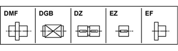
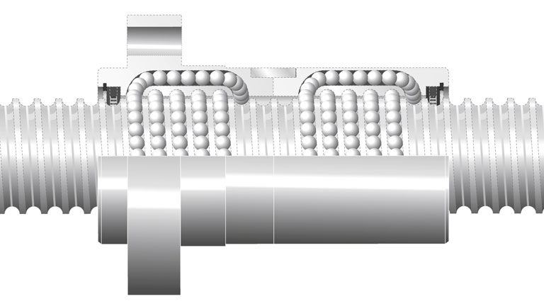
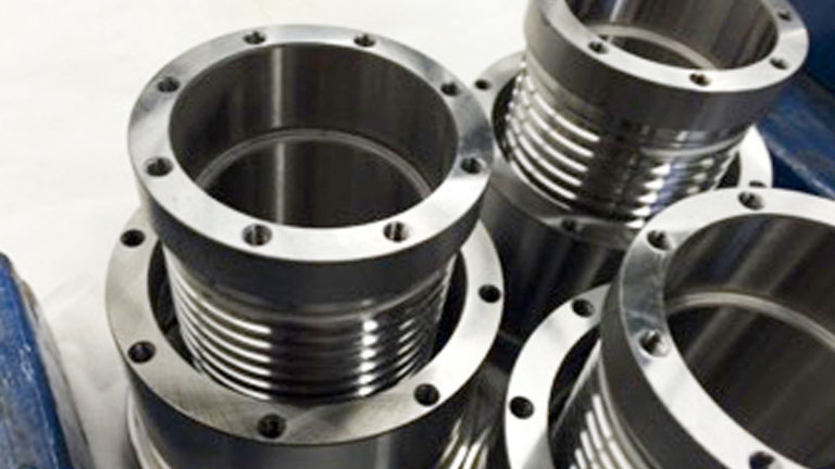
Different nut designs, some with flange mounts
Ball Raceway Profiles of Ball Screws
The geometry of the ball raceway profiles is not subject to any superordinate specification (standard) and is determined by the manufacturer of ball races and their expertise. That is why ball screws from different manufacturers with the same design and installation size are almost always manufactured with different ball raceway profiles. A spindle-nut combination from different manufacturers is therefore usually not possible and also does not make sense in view of a reliable functionality.
The ball raceway profile greatly affects the load bearing capacity and running quality of ball screws. With precision ball screws, for example as they are used in machine tools, the ogive profile (also called Gothic profile) has developed into a proven standard, since the most important quality-determining variables (such as osculation and pressure angle) are structurally very predictable and controllable.
Hybrid Ball Screws with Ceramic Balls
Another distinction is possible through the power-transmitting balls themselves. Balls made of high-strength hardened steel (100Cr6) are used in most ball screws. They are characterized by a high load capacity and a high wear resistance. In addition, they can be manufactured very precisely and economically.
However, balls made of silicon nitride have also been installed in ball screws for some years now. In these so-called hybrid ball screws, the ceramic balls roll on the steel ball raceways of the spindle and the nut. The ceramic balls are characterized in particular by a high load capacity, low friction and very favorable emergency running properties in the event of a lack of lubricant. However since the load bearing capacity of a ball screw not only depends on the balls, but also on the ball raceways on the spindle and in the nut, a significantly higher load capacity of hybrid ball screws is not necessarily a given. This design without a doubt has advantages at low travel speeds due to the extremely favorable friction conditions.
Different Installation Positions of Ball Screws
The installation position (horizontal or vertical) of a ball screw is generally arbitrary and in principle does not directly affect its function. However, it may affect the load, the lubrication strategy (increased loss of lubricant) and in some cases also the vibration and noise behavior (ball drop in the ball return).
Horizontally installed ball screws, for example, usually travel on a carriage between two points, whereby the carriage mass is accommodated by the guides. Since the travel direction often does not matter and has no preferred direction, horizontally arranged ball screws in the operating state are almost always loaded with virtually equal forces on both sides.
In the event of vertical application, the carriage mass rests on the nut and must be raised or lowered by the ball screw. In this application case, the ball screw is normally loaded on one side with a preferred direction. The load may be reduced through suitable weight-relieving measures, which benefits the durability of the ball screw. However, this requires additional structural machine effort, which is also reflected in the manufacturing costs of the machine.
Most applications of ball screws occur in the horizontal or in the vertical installation position, even though these are only the extreme positions of the generally applicable slanted installation position.
Manufacturing Methods
Various production methods may be used when manufacturing ball screws. Ball screws are therefore available in rolled, twisted, through-hardened or ground designs. Since the manufacturing method directly affects the accuracy and load bearing capacity and therefore ultimately also the usability of a ball screw, it is very important to choose the correct production method.
Thread Grinding, Maximum Precision
Maximum precision is achieved by grinding the ball screw as a final finishing after heat treatment. Ground ball screws are produced at AM in the precision accuracy classes IT 1, IT 3 and IT 5. The average roughness depths of the ball raceway surfaces lie at Rz1 and the arithmetic average roughness value is Ra0.15. Due to the high dimensional accuracy of the nut and spindle, ground ball screws are characterized by a very uniformly smooth and low-vibration running behavior. They have a very long service life and a very high load bearing capacity and long-term accuracy throughout the entire service life.
Grinding is the traditional manufacturing method for the hard machining of ball screws. However, this production chain is also the most cost-intensive due to the large number of individual processing steps and the processing machines required. That is why the optimal utilization and coordination of modern grinding technologies on efficient grinding machines is absolutely necessary for an economic production.
Thread Whirling of the Profile Contour
Normally, ground ball screw spindles are prepared with a grinding allowance in the thread flanks. This preparation is done by whirling the thread before the heat treatment. Whirling is an impact-turning-milling process where the profile contour is machined out of the spindle with a whirling head equipped with cutting inserts. The whirling unit is used in the pitch angle of the ball screw and is moved axially along the spindle at a feed rate corresponding to the desired pitch. The whirling gyroscope rotating around the spindle rod is moved radially out of the axis middle so that it cuts the material with very small chips.
The already good production accuracies can be achieved through the whirling process so that this production method is also suitable for finish machining. This in particular applies when whirling into hard material. However, the process creates surfaces with a high number of facets, which may negatively affect the running quality of the ball screw. Hard whirling is often also called thread peeling.
Materials and Heat Treatment
The selection of materials and the wear-determining heat treatment of ballnuts (through-hardened) and ballscrews (surface-hardened, deep-nitrided) are very important when it comes to economical production with high quality and long durability. A high hardness (67 HRC) of the ball tracks is the basic prerequisite for a long service life of the ball race. It makes the ball screw insensitive to high loads and external influences, such as metal chips.
Areas of Application
The structural design and the manufacturing method of the ball screw are ultimately determined by its use. In addition to "normal" application areas, ball screws can also be used in the high-speed range, in the heavy-load range, in the short-stroke and oscillation range (micro-move) as well as in the smooth running range (e.g. grinding drives). However, ball screws can also be safely used under special ambient conditions, such as under water or in high temperatures. The technological demands and the set expectations are very dependent on the application in the individual application areas. They are very specific and even contrary sometimes. A ball screw that can bear a very high load, for example, will never also have to realize very high travel speeds. In contrast, a highly dynamic ball screw is loaded with comparatively low forces. If a large mass is to be moved in small steps, then usually no high dynamics are also required, but rather a low breakaway torque and a very low friction are expected. That is why special structural designs are necessary that correspond to the respective application profile as precisely as possible.
Ball Screw Types P and T for Positioning and Transport According to DIN ISO 3408
Another distinction among ball screws is the usage purpose, whereby a distinction is made between positioning and transport ball screws according to DIN ISO 3408.
Positioning ball screws (type P according to DIN ISO 3408-1) are backlash-free preloaded systems that are normally used for positioning tasks or in applications with increased requirements (e.g. machine tools). The ball screw ground to very tight dimensional tolerances allows for the indirect measurement of the path from the rotational angle and the thread pitch. The travel accuracy is determined by the path deviation of the ball screw.
Transport ball screws (type T according to DIN ISO 3408-1) are used to move components. Typical applications include handling axes, for example. The spindle thread is not always necessarily ground, but rather is often rolled or whirled. The accuracy requirement of a transport ball screw is much lower than that of a positioning ball screw. However, if a parallel arranged linear measurement system is used to determine the position of the axis for transport ball screws, then the positioning accuracy will no longer be determined by the ball screw, but rather by the resolution and thus by the accuracy of the path measurement system. Better positioning accuracies can be achieved here with transport ball screws than with positioning ball screws. In these applications, the ball screw spindles are usually also ground due to the improved durability and required running quality.
Multi-Spindle Application
Ball screws can also be used as multi-spindle systems, whereby the power transmission and the movement implementation are not realized by one ball screw, but rather are realized by several (usually two) parallel arranged systems. The control system manufacturer offers special operating modes (e.g. master-slave operation or gantry operation) with a very high level of uniformity for this very demanding control technology drive task. The pitch deviations of the parallel arranged ball screw spindles with each other should be as small as possible so that there is no bending out of line or tilting in the movement guides. The control quality of the synchronous travel movements of both spindles in all movement phases is also very important. The force distribution of the load is also very important, since for example in the event of a temporally changing moving load this does not always affect the same parts on the individual ball screws, but rather there may be considerable differences. Since the movement behavior and the force distribution cannot always be predicted, there may be very high additional loads on each ball screw.
Precision Ball Screws for Maximum Performance
Precision ball screws require the perfect interplay between nuts, balls and ballscrew shaft. The individual parts ground in very tight tolerances are brought to the highest level of precision through the manual assembly by highly skilled specialists.
Only the highest quality materials are used to produce the components. The wear-resistant, long-term nitrided surfaces of all of the ballscrews as well as the through-hardened nuts and balls, optimal ball recirculation systems and effective wipers guarantee the high load capacity and precision over a very long useful life.
The high geometrical accuracies and the preload of the double nuts in 2-point contact during assembly are the basis for the high nut rigidity with simultaneously very low inner friction. This is also reflected in the very high system efficiency and in the low idling and breakaway torques.
The even torque curve, the high level of smooth running and the lowest possible vibration tendency over the entire thread length minimize the power loss and therefore also the heat development, regardless of whether the ball screw is lubricated with oil or with grease.
The installation and load direction of precision ball screws is generally arbitrary and does not affect its functionality.
The designs and the connection dimensions of the precision ball screws are conform with DIN ISO 3408 or DIN 69051 or correspond to individual customer requirements as special designs.
What distinguishes precision ball screws from A.MANNESMANN
- Perfect interplay of nuts, balls and ballscrews
- Precision-ground nuts and shafts in the tolerance classes IT 1, IT 3, IT 5
- High-precision graded balls
- Optimal ball recirculation systems
- Effective wiper systems
- High quality materials for nuts, balls and ballscrew shafts
- Wear-resistant surfaces of the entire shaft (ball raceways and spindle pivots)
- Long-term nitrided
- Tough elastic spindle core
- Through-hardened nuts (100Cr6)
- Very high surface hardness (67 HRC)
- High geometrical accuracy of the nut
- High load capacity
- Long durability
- Double nut with preload (2-point contact)
- Adjustable preload
- Keys to secure the preload
- High nut rigidity
- Low friction
- Low power loss
- Low heat development
- Low idle torque
- Low frictional torque
- Low breakaway torque
- Constant torque curve
- High level of smooth running
- Low vibration generation
- Suitable for oil and grease lubrication
- Manual ball screw assembly
- High quality assurance
- Based on DIN ISO 3408 or DIN 69051
Ball Screw Nuts - the Functional Guarantors
The ballnut is the most complex component of the ballscrew assembly. The perfect functioning of the ball screw depends especially on the ballnut, as it contains the ball bearings, the ball return units and the wipers. The preload is generated via the nut if necessary, which on the one hand serves to avoid backlash and on the other hand increases the rigidity.
The Highest Demands on the Material and Design of the Nuts
As the ballnutnut is not only carries rolling motion of the balls in the ball-track, but also in the ball return, it is subject to a constant load, unlike the screw. The operating temperature on the nut surface is therefore always slightly higher (about 5K) than the temperature on the screw surface. So that the ballnut can safely bear the high load over its entire service life, the nut is normally made of high-quality ball bearing steel (100Cr6) and is through-hardened.
If the screws are always custom-made due to the required stroke lengths, the ballnuts may be subject to a certain dimensional standardization. This may be done in the dimensions according to DIN ISO 3408 or DIN 69051 or also specific to the manufacturer. However, some ballnuts, which meet these requirements, are custom special components in many applications.
Requirements for Different Nut Designs
Despite all efforts for standardization, there are different nut designs depending on the requirements and installation situation. The first distinguishing criterion for ball screw nuts is the number of nut body parts. A distinction is made here between single nuts and double nuts. However, more than two nut parts may be necessary for a nut system due to the technical manufacturing needs.
Double Nut or Double and Triple Nuts
The double nut is the traditional nut design that is very popular, especially in machine tool design, as preloaded systems with 2-point contact are used here almost exclusively. Both ballnut parts are mounted so that the balls are clamped between the ball raceways of the spindle and the nut. The axial displacement is provided by ground intermediate washers or by twisting the nut parts to each other. In both cases, the distance between the loaded turns of both ballnut parts is increased or decreased.
The double nut is the traditional nut design of a ball screw. It normally consists of two parts, whereby one part (as a load carrying ballnunut) absorbs the extrenal load and the other ballnut part (as the preload nut) generates the preload. The load nut is always the ballnut part through which the axial force is guided into the direct distribution of forces.
Depending on the distribution of forces, O or X-preloads can be generated in a double nut. For technical production reasons, the ballnut nut parts can also be designed as two parts when it comes to double nuts so that a three-fold or four-fold ballnut is also possible.
The double nut can be designed both as a cylindrical nut as well as a flange nut. Both nut parts are geometrically identical with the cylindrical nut. The preload is then externally applied as an X-preload over at least one spacer.
With the flange nut, a distinction is made between the component with the flange and the lock nut (without flange). The preload is then always generated from the inside as an O-preload through the axial displacement of the loaded turns. This displacement may occur both via intermediate rings as well as through the distortion of the nut parts.
Double nut
Single Nuts
The single nut is the most compact and lowest cost nut design. This is why it is very widespread and only consists of a nut body part with a continuous ball-track. In the simplest design, single nuts have a slight axial clearance.
Backlash-free preloaded single nuts are also possible by varying the loaded turns and/or a ball sizing as well as the structural design. Due to the imperfect running behavior of these designs, the preload is usually associated with increased friction, increased operating temperature and increased wear. Single nuts with preload are slightly more sensitive to production tolerances so that very long spindles are normally not equipped with preloaded single nuts. This does not apply to single nuts without preload, since they always run in 2-point contact under axial load. For single nuts with a 4-point contact, there cannot be ball relief during load peaks and therefore there cannot be sliding balls, since the load transfer and the preload occur via the same balls.
Preload through Ball Selection
The easiest way to eliminate play in a single nut is to use ball selection. These balls are larger than the gap between ballnut and screw, which is determined by the four ball raceway edges on the spindle and in the nut. The balls must be placed under force into this gap that is too small. 4-point contact exists due to the elastic flattening on the balls and in the ball raceways. Since DIN ISO 3408 does not apply as a basis for calculation for 4-point contact, the preload size must be determined empirically.
The amount of the preload is not variably adjustable with ball selection, but rather depends solely on the excess size of the balls and requires that the prescribed thread design is precisely achieved by production. The structurally specified locations of the ball support points must also be achieved during assembly. Only then is the preload force detectable and present in the single nut.
Preload through Pitch Offset
For two or multi-circuit ballnuts, the preload can also be achieved with single nuts through the pitch offset of the thread pitch between the individual circuits in the ballnut. Due to this offset, the balls in each circuit run independently of each other on a different edge of the spindle thread. The preload occurs through the ball on both edges in 2-point contact. The preload size is determined by the manufactured pitch offset. The preload can be modified through an additional ball selection.
Preload through Thread Shifting
Thread shifting is also possible in the nut to be able to preload single-run ball screws. In this process, the middle loaded circuit is produced with a steadily increasing lead shift. The balls thus run on one edge of the thread, with play in the middle and then switch to the opposite edge. The preload also occurs here through the balls on both edges in 2-point contact. The preload size is determined by the manufactured shifting. The fine tuning of the preload can also be done through ball selection.
Preload through Slotted Nuts
Another way to make backlash-free single nuts is axial slitting and twisting of the nut body. The width of the slit in the nut body is changed by a clamping screw. This reduces the ball track diameter, resulting in a preload with 4-point contact when combined with ball selection. However, in addition to the ball track geometry, the roundness in the nut thread also changes so that the preload and the running behavior of each ball are not constant and uniform.
Different Nut Designs
A second distinguishing criterion is the outer contour or the fastening type of the nut. In addition to the cylindrical design, the flange design is also important.
The two nut body parts must always be mounted in a housing for the preloaded cylindrical design via a double nut. The preload then occurs from the outside to the inside via pressure flanges. The preload is limited via a spacer between the nut parts. An X-preload always results here.
The mounting flange is always a fixed component of the nut body with flange designs (with side or middle flange). The preload is generated via the lock nut part by twisting both nut parts towards each other or via an adjustable intermediate washer from the inside to the outside. The lock nut is only held in the ball raceways by the balls and the applied preload force. The adjustment of the variable preload force is an individual assembly process, which can be very well matched to the application case and creates optimal conditions for high load capacity and long durability.
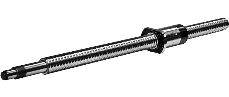
Ball screw with double nut with side flange
Ball Screw Spindle as a Load-Bearing Component
The ball screw spindle is the component part of a ball screw assembly that carries the nut. It is a cylindrical shaft and generally consists of at least two sections. One section bears the helical ball track through which the movement kinematics of the ball screw are implemented in its full length. The spindle thread is always loaded only sequentially (partially, temporarily) in the current ball contact area. The support bearing and possibly the drive connection are located on the other section(s). The forces and torques in the ballscrew are introduced into or dissipated in the machine environment.
Influence of Spindle Length and Execution
The thread length of the spindle is normally determined by the active travel of the application, the total length of the nut (including the wiper system and other accessories) and the thread runout. Depending on the length and design, the ball screw spindle is mounted on one or both sides so that the entire length of the ball screw spindle may be significantly longer in parts than the thread length. The entire spindle length and the structural bearing design are crucial for the buckling and rotational stability and thus for the speed and load-dependent applicability of the ball screw.
The A.MANNESMANN ball screw spindle precision-ground in very close tolerances (IT 1, IT 3, IT 5) is produced from high-strength nitrided steel, whereby the entire ballscrew form is deep-nitrided. It has a tough spindle core and a surface hardness of app 900 HV (= 67 HRC) with a hardening depth of at least 0.4 mm. This very high surface hardness is the basis for a high load capacity and a long service life.
Structural Determination
The structural determination of the spindle design is usually done by the user of the ball screw. It depends greatly on its task and the machine environment. The influence of A.MANNESMANN as a ball screw manufacturer is therefore usually focused on optimizing the function and production possibilities as well as on ensuring the quality required by the user.
The ball screw spindle is characterized by the thread diameter, thread pitch, pitch direction, ball size, thread length, accuracy class and by the thread profile and number of runs of the ball screw. The dimensioning and design of the support bearing and drive connection depend on the usual dimensions of the bearing types and their mounting needs or on the shaft-hub connections of the drive elements.
A spindle standardization is nearly impossible due to this individual design.
Different Spindle Designs
The structural design and geometric implementation result in some basic spindle versions that are not only technically very different from each other, but also are economically very different from each other. The individual distinguishing features are sometimes very significant, but are not always directly obvious.
Regardless of whether the ball screw spindle is designed to be driven or non-rotating, certain functional or production reasons may require special designs that do not correspond to a "normal" solid spindle. These include spindle designs such as:
- Hollow spindles
- Spindles with collars
- Coupled spindles
- Corrosion-resistant spindles
So that these ball screw spindles can also be produced in high quality, sometimes very different specific influences must be taken into consideration when producing ball screw spindles in special designs in addition to taking the already necessary care. Certain design-related limitations may occur when using such ball screw spindles.
Solid Spindles
Most ball screw spindles are designed as solid spindles. The spindle cross section corresponds to that of a solid spindle (without bore). Power is transmitted over the entire cross-sectional area with the corresponding tensile, compressive and torsional stresses.
Since the required processing effort is the lowest, the solid spindle is not only the simplest when it comes to manufacturing technology, but is also the most cost-effective design option.

Ball screw with solid ballscrew shaft
Hollow Spindles
If the ballscrew shaft requires a central bore, for example for cooling or lubricating tasks, or different functional components need to be installed in this space, then the ball screw spindle can be designed as a hollow spindle. The spindle cross section in this case corresponds to that of a pipe with a corresponding wall. However, the pipe wall must at least be dimensioned so that the axial load and the torque can be transmitted without deformation and safely while taking the thread groove depth into consideration.
Advantages of Hollow Spindles
Using hollow spindles has various technical advantages. For example, the critical bending speed can be increased further by hollow boring the spindle. It is interesting that the critical bending speed constantly changes at otherwise constant spindle dimensions with an increasing internal diameter of the spindle. There is theoretically no saturation point from which the critical bending speed no longer increases. Of course the exact production of such hollow spindles is problematic. The lower mass moment of inertia of hollow spindles is also advantageous.
If a fixed-fixed bearing is used, it is possible to use the bore of the hollow spindle for a cooling medium in order to keep the spindle temperature as constant as possible during the machining process. The necessary stretching forces are minimized here and pitch errors of the spindle are reduced as a result of thermal expansion.
If the spindle body has a fixed-fixed bearing and not the conventional fixed-loose bearing and is also hollow bored, then the loss of axial rigidity will be more than compensated for as a result of the hollow boring through the fixed-fixed bearing.
Hollow spindles have lower masses, lower rigidity and usually only lightly lower mass moments of inertia compared to corresponding solid spindles.
Since the inner contour of the hollow spindle is usually already made before the heat treatment, this is then also correspondingly hard (nitrided). Due to the lower masses, the temperature-related geometry changes of hollow spindles are larger during production. This leads to an increase in the diameter and above all to an extension of the spindle, which can also affect the thread pitch. Hollow spindles are usually much more processing-intensive and therefore more expensive to manufacture.
Ball screw with hollow ballscrew shaft
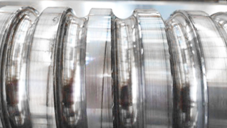
Spindles with Collars
The outer diameter of the ball screw shaft is usually the largest diameter from which all other shaft diemensions are worked out. It may be necessary under certain conditions to use larger diameters in individual shaft areas than the outer diameter of the ball screw. For example this may be the desire to have a larger contact shoulder for a spindle bearing and/or to achieve greater rigidity and stability in the spindle shaft. Such ballscrew shafts are designated as ballscrews with collars.
Because the spindle diameter is larger on one side, the ball screw nuts can only be mounted on one side with screw shaft with collars. Ballscrews with collars can also have the larger spindle diameters in the spindle middle as well. With this design, the spindle then for example usually has a right-handed and left-handed ball screw alternately and is equipped with two nuts. The largest spindle diameter in the spindle middle is also used to accommodate a support bearing.
Since the outer diameter of the next larger nominal diameter often has to be selected as the output variable for reasons of material scheduling, the necessary machining effort to produce such a spindle is considerable. In addition, the collar is disruptive when grinding the ball screw.
Increased Production Effort
If the costs for this additional effort are greater than the additional material costs, then the production of a larger spindle is usually more economical. With larger spindles, however, it must be taken into consideration that the installation dimensions of the nut must also be increased and at the same time this increased space requirement must exist in the available installation space.
Sleeves and Rings as an Alternative
To circumvent the need for a spindle with collar design, sleeves or rings can be provided instead of the collar depending on the objective (e.g. with enlarged contact shoulder for the bearing). In these cases, the stable contact shoulder is made through these rings, which are installed after grinding the thread. These components can either be loosely threaded, adhered or shrunk.
The advantage of adhered support rings is that these can still be finely adjusted until right before the final adhesion. The adhesive Loctite 603 can usually be used for bonding. The bond can also be easily released again with the corresponding addition of heat. To avoid the adhesive getting into the loaded turns or into the nut, it must be ensured during bonding that only the bore surface and not the front face is wetted with adhesive.
With shrunk support rings, it must be ensured that the ring is applied fully to the installation edge without a gap, since it can no longer be aligned or displaced later on. It is only possible to disassemble the ring by using large forces and it usually cannot be done without destruction. Due to the significantly higher production costs, screw shafts with collars should only be used when it is absolutely technically necessary and there is no practical alternative solution.
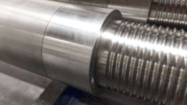
Spindle with collar with thread and locknut
Coupled ballscrews for Excess Lengths of up to 25 m.
The maximum length of a ball screw shaft is usually limited by the availability of the raw material and the production capabilities (e.g. grinding, nitriding). To be able to produce longer spindles if required, it is also possible to permanently couple two ballscrews. Two finish-ground connecting screws are aligned here so that the threads run exactly into each other. The screws are used to connect the mating faces of the 2 ballscrew shafts. The rigidity at the joint is additionally reinforced by the opposite pitch of the 2 connecting screws (right and left-handed).
The spindles aligned in this way are form-fit by means of a coupling point specifically developed for this purpose. If the travel deviations of both spindle pieces are almost identical, coupled spindles normally do not result in any notable reductions in quality. Theoretically, any length of spindle can be produced through several coupling points.
Coupled ball screw spindle
Exact knowledge of the ball screw use and the existing distribution of forces is very important when designing and evaluating the coupling point. The coupling point is usually only loaded with the occurring axial force for ball screws with driven nuts. If the spindle is driven, the drive torque in the spindle is also added as a load in addition to the axial force.
Please describe your application case to us. Our experts will advise you individually.
Applicability
Coupled ball screws are normally only used in a horizontal position. Due to the possible axial tensile load, and for safety reasons A.MANNESMANN does not produce vertically suspended ball screws in a coupled design.
Thread Length
The thread length of a ball screw is decisive for the total length of a ball screw shaft. It consists of the useful travel, the runouts on both sides and the length of the nut body. The useful travel lu is the maximum possible travel of the nut through which the required accuracy is applicable. It should be dimensioned larger than the structurally intended nominal travel of the axis and is usually limited by end stops and/or limit switches. The pitch-dependent runout le has no accuracy requirement, since it is normally not traveled. The installation lengths for the wiper may also need to be considered for the nut length l2.
Spindle Details
In order to completely ensure the functionality and quality of a ball screw , various details are to be taken into consideration during ballscrew shaft production that can only partially or not at all be assigned to the ball screw. These include, for example:
- Bearing jpurnals
- Support journals for drive components
- Thread runouts
- Undercuts
- Centering
- Mounting thread
- End tapped holes
- Spanner flats
- Rotary encoder connections
Accuracy of Screws
The accuracy of a ball screw is determined by the thread pitch and the associated path deviation based on the travel. The path deviation of the nut is always less than the pitch error in the ball screw shaft, since the pitch tolerance of the nut somewhat dampens the effect of the spindle pitch error. This accuracy ultimately decides the usability of the ball screw as a positioning or transport ball screw.
Direct to our service
Your request to us
Use our professional competence to develop the best solution. Our engineers can be reached directly under
+49 2191 989-200
Downloads
In our Download Center, you will find all of the information that we provide you as files for downloading, arranged by category.
Downloads for this Product

ball screws folder 8.94 MB
Ball_screws_Precision_ground_new 0.99 MB

characteristics ball screws 16.00 KB
company profile 478 KB
enquiry ball screws 1.90 MB
telescopic ball screws 7.80 MB
Zertifikat_DIN_EN_ISO_9001 1.49 MB
Direct to our service
Your request to us
Use our professional competence to develop the best solution. Our engineers can be reached directly under
+49 2191 989-200