Overview of Ball Screws with Driven Nuts
With a ball screw with driven nut, the rotating drive motion of the nut is converted into a translatory movement of the screw shaft relative to the nut.
Since the nut rotates around the spindle with this ball screw principle, the imbalance of the nut acts on the stationary spindle and the machine environment. The critical vibration speed of about 25% is above the critical bending speed here. These vibrations can not only affect the machining quality of the machine, but also lead to increased wear in the feed axis.
The balancing surfaces on the nut body, which reduce the resulting residual imbalance to a minimum, are therefore characteristic of high-quality driven nuts from A.MANNESMANN. All driven nuts are statically balanced in the balancing quality Q2.5.
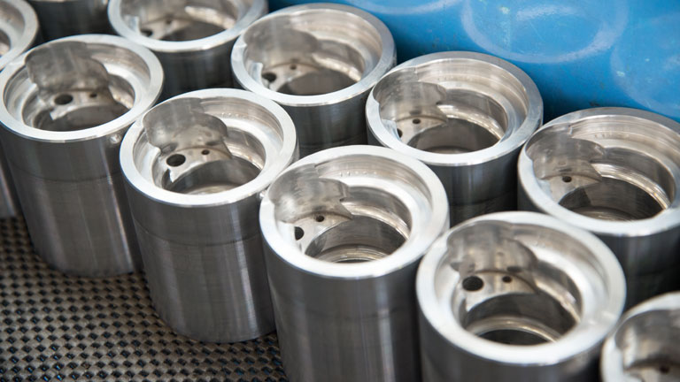
Nut production for ball screws
High Flexibility in Application
Depending on the task, the use of ball screws with driven nuts may be advantageous.
Ball screws with driven nuts can realize longer travel, higher speeds and therefore also higher travel speeds compared to driven spindles. In addition, it is possible to place several nuts on one central spindle and to move these individually with separate drives.
Even use where the spindle and nut are driven is possible for corresponding tasks.
Application Areas
Precision ball screws with driven nuts are used when long axis paths are to be managed as quickly as possible, such as in plastic injection molding machines, with large broaching machines and in various lifting equipment. Speeds are required here that reduce the cycle times for long paths and therefore decidedly determine or increase the economic efficiency of machines.
Ball screw with driven nut in application

Economical advantages
- Lowest cost standard version
- High speed
- Quick cycle time
- Low power loss
- Excellent energy efficiency
- High long-term durability / service life
- Maximum long-term precision
- Maximum possible machine availability
- Perfected wear resistance due to nitrided spindle
- Economical standard designs or custom production
Technical advantages
- Driven nut
- Long travel
- Minimum residual imbalance of the nut body (balancing quality Q2.5)
- Critical vibration speed determines the application limits (speed characteristic value of dn x n (nominal diameter x speed) < 220,000)
- Higher speeds (up to 35% higher than with the driven spindle)
- Higher travel speeds than with the driven spindle
- High precision and efficiency
- Very long service life
- High nut rigidity
- Low friction
- Low idle torque
- Fixed bearings, no heating, reduction of power loss
- Simple liquid cooling
Driven Nuts
Driven (rotating) nuts with a stationary ballscrew shaft have various advantages compared to the normal configuration with a rotating spindle. Since the screw shaft does not rotate, fixed bearing arrangements are sufficient for support . The screw shaft can also be easily and efficiently cooled via a central bore and fixed screw connections for the coolant. It is possible to use stretched spindles, especially with longer spindles.
Higher Speeds and Travel Speeds with Driven Nuts
Since the nut rotates around the spindle (shaft or axis), it acts like a vibration exciter. So that it generates as little vibration as possible and a vibration of the spindle shaft occurs later from resonance phenomena, the nut must have a good concentricity and above all a low residual imbalance. With long non-rotating shafts with driven nuts, up to 35% higher speeds and therefore also higher travel speeds can be achieved.
Dissipating the Stretching Forces via Fixed Bearings - without Heating
Stretching the spindle shaft is easier than with a rotating spindle, since the stretching forces are not passed through rotating bearings, but rather through fixed bearings into the surrounding structure. There is no heating of the bearings and therefore there is reduced power loss.
Simple Cooling
The liquid cooling of the spindle is facilitated because the supply of the coolant cannot occur via rotary feedthroughs, but rather directly through fixed screw connections in the spindle.
Higher Spindle Rigidity
The torsional and axial rigidity of the spindle shaft is increased, since axial forces and torsional moments on both ends of the spindle are dissipated into the surrounding structure. This significantly improves the rigidity, especially with spindles with high pitch diameter ratio, which is not achievable with rotating spindles.
Double or Triple Nut Operation
A stationary ball screw spindle can accommodate several ball screw nuts as well. If these nuts are driven individually, then the movements of the nuts can be used independently of each other.
The advantages of rotating nuts are offset with some system-related disadvantages.
Complex Lubricant Supply
The lubricant supply from the outside directly into the nut is difficult, since rotary feedthroughs are required and the centrifugal forces make it impossible to transport the lubricant to the balls and ball raceways. The rotary feedthroughs for the lubricant supply in a rotating nut are problematic, since they (possibly also only after some time) may have a leak that is higher than the normal lubricant flow rate of a ball screw nut. The result may be that the oil, which is pressed against the shaft seals of the rotary feedthrough by centrifugal forces, is lost and the lubrication of the balls and raceways fails completely.
As a remedy and to save the rotary feedthroughs for the lubricant, the nut can be supplied through a lubrication channel in the spindle. For this purpose, in addition to a possible cooling hole through the spindle, a deep hole is made parallel to the axis up to the tool change position of the nut and the lubricant is sprayed into the nut through a transverse hole when the nut is right at this point. The amount of lubricant then usually easily suffices until the next tool change.
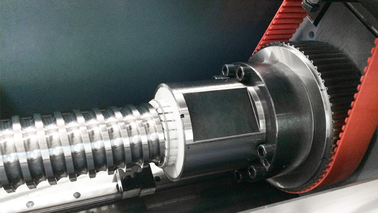
Belt or Gear Wheel Drive With Axial Bearing
Driven nuts should be mounted axially on a displaced spindle if possible, which are driven via a belt or gear wheel drive. The heat generated during operation can be released into the environment easily through the nut body.
When designing the belt drive and the bearing, it must be ensured that the belt tensile forces are completely absorbed by the bearing and the nut is not additionally radially loaded, for example from the belt preload.
The necessary thrust bearings can be relatively large in diameter and in some circumstances limit the travel speed. In order to minimize the bearing bore diameter and to increase the speed limits of the bearing, the bearings are often directly mounted to the nut body. In this case, the thread for the clamping nut of the bearing is integrated directly into the nut body.
Running Behavior with Minimized Residual Imbalance
Since the nut does not have any homogeneous mass distribution due to the loaded turns and the ball return, the resulting imbalance in the rotation around the spindle is very noticeable in the running behavior. Driven nuts must therefore be finely balanced through tare pads or other balancing measures. The constant change of the residual imbalance due to the changing ball positions cannot be completely compensated.
Drive via Hollow Shaft Motors with Cooling System
A direct drive is only possible with hollow shaft motors, which may however be problematic with respect to heat emission in the nut and requires a cooling system to avoid any thermal impairments.
Critical Vibration Speed
The dynamic application limits for precision ball screws with driven nuts are determined by the critical vibration speed or the mass forces acting on the balls during operation.
The speed characteristic value of dn x n (nominal diameter x speed) < 220,000 applies as a reference value for precision ball screws with driven nuts.
Standards and Custom-Made Production
A.MANNESMANN supplies these standardized precision ball screws (AM 2.52) as a double nut with side flange, preloaded in the nominal diameters of 32, 40, 50, 63, 80, 100 and 125 mm with all the common thread pitches and in the accuracy classes better than IT 5.
Of course as a manufacturer, we also produce special diameters. Please just send us your inquiry.
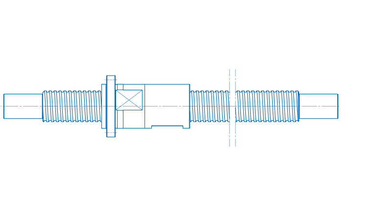
Ball screw with driven nut
Characteristic Values of the Ball Screws
In addition to the dimensions, the load ratings, the nut rigidity and the idle torque are the classifying characteristic values of ball screws. The load ratings describe the load bearing capacities of the ball screw during movement (dynamic) and at rest (static). The dynamic load rating is also the basis for calculating the service life.
The nut rigidity is the measure for the axial force, which is required for deformation in the ball transition contact. The idle torque is the characteristic value for the internal system friction. Together with the nut rigidity, the preload can also be closed via the idle torque.
You will find the characteristic values in the technical data sheet of each ball screw.
Rotatory Mass Moment of Inertia
The rotatory mass moment of inertia (Js) of the ballscrew shaft is usually required for designing the motor. With driven solid screw shafts, this (with a good approximation neglecting the thread geometry) corresponds to the cylindrical spindle body with respect to its axis of rotation.
Here the ball contact diameter dc on the spindle with the 4th power, the spindle length ls and the density of the spindle material rs are decisive. The mass moment of inertia Js is usually specified in kgcm2. If the rotatory mass moment of inertia Js is related to the spindle length of one meter, then it can easily be converted by multiplying the ratio of the existing spindle length with one meter.
Spindle Torsion
The spindle is normally driven by a motor. The motor's drive torque is guided through the spindle to the nut and there converts into an axial force. In the slim spindle, this results in a torsion due to the torsional moment that exists. The torsion length, the torsion angle and therefore also the torsional rigidity depend on the axial nut position on the spindle. Since this can change variably in operation due to the axial displacement, the torsional rigidity is also not a constant characteristic value.
The maximum torsional stress of the spindle (can usually also be assumed to be a circular full cross-section) can be determined from the torsional moment or torque (T) and from the polar modulus of resistance of the ball screw spindle (Wps) or the spindle diameter.
The torsion angle (torsional angle) is dependent on the spindle length or on the position (I) where the torque acts and on the shear modulus (G) of the spindle material. To calculate the torsional angle, the moment of area of the 2nd order (Ips) and the torsional moment (T) are also required.
Since the effective position (I) varies depending on the axial travel movement of the nut, the torsional angle (j) is also not a constant value, but rather is a function of the length (I). However, torsional angle is also directly dependent on the time variation of the effective torque, whereby it is also to be seen as a function of time. That is why torsional vibrations that temporally vary depending on the torsion are created, which also act in the axial direction through the ball screw.
Tensile and Compressive Load
In addition to the torsional load, a driven spindle is mainly loaded by tension or pressure. In both cases, the tensile or compressive strength of the spindle are the load limit values.
When evaluating the load, it is important to take the correct "smallest" spindle cross section into account. Only the cross-section that lies in the spindle's distribution of forces is relevant for determining the tension. With the tensile load, the determining spindle cross section usually does not lie in the area of the ball screw, but rather in the area of the mounting thread of the bearings. The buckling stability is also to be noted, since there is a risk of buckling in the event of a compressive load on particularly long spindles.
Characteristic Value Calculations
As part of our service, we offer you the calculation of the most important characteristic values. We would like to support you in your planning from an early stage.
Get in touch with us by sending an e-mail to salesamannesmannde with the subject "Characteristic value calculation" or by phoning us at +49 2191 989-0 and give us the following parameters of your desired ball screw:
- Nominal diameter d0 [mm]
- Pitch P [mm]
- Ball diameter DK [mm]
- Spindle length Ln [mm]
- Bearing selection: Bearing A, bearing B, bearing C, bearing D
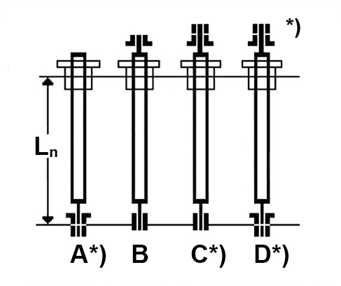
*) Directionally stable clamping
Direct to our service
Your request to us
Use our professional competence to develop the best solution. Our engineers can be reached directly under
+49 2191 989-200
Downloads
In our Download Center, you will find all of the information that we provide you as files for downloading, arranged by category.
Downloads for this Product

ball screws folder 8.94 MB
Ball_screws_Precision_ground_new 0.99 MB

characteristics ball screws 16.00 KB
company profile 478 KB
enquiry ball screws 1.90 MB
telescopic ball screws 7.80 MB
Zertifikat_DIN_EN_ISO_9001 1.49 MB
Direct to our service
Your request to us
Use our professional competence to develop the best solution. Our engineers can be reached directly under
+49 2191 989-200